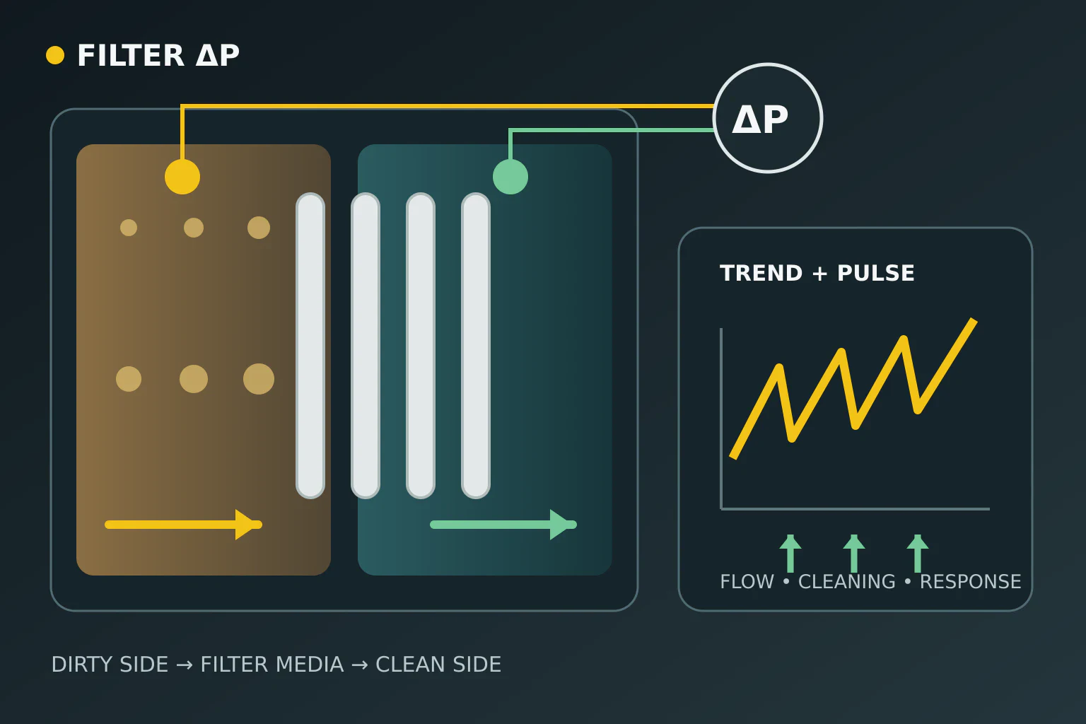
Differential pressure in a pulse-jet filter is the pressure difference between the dirty-air and clean-air plenums. It makes resistance across the filter surface visible, but does not prove bag condition by itself. The same pressure drop means different things at different airflow rates. Diagnosis therefore requires reading its trend together with airflow or fan load, cleaning pulses, inlet temperature and product condition.
Fix the comparison condition first
Differential pressure depends on resistance as gas passes through the filter medium and dust cake. Raising airflow can increase the value even with clean, intact media. The EPA operation manual specifically states that values should be compared at the same volumetric flow when evaluating fabric change. If airflow is unavailable, fan frequency, damper position and fan current provide context. They are not substitutes for airflow, but show whether the operating point changed.
New filter elements do not provide a permanent reference during their first hours. As a stable dust layer develops, initial resistance and residual pressure drop after cleaning can change. Establish the reference band with the same product, similar moisture and temperature, the same fan setting and steady production. Instead of one shift value, retain a timestamped trend containing minimum, maximum and post-cleaning values.
Separate high, low and cycling trends
A differential pressure that rises slowly at constant airflow can relate to insufficient cleaning, permanent blinding, moisture or dust that is not removed from the hopper. After a sudden rise, first check fan operating point and damper changes; then review pulse-air pressure, valve sequence and product condition. A high value alone is not a bag-replacement decision. The response to a cleaning pulse and the level reached afterwards are more informative.
A sudden drop can hide two different scenarios. If airflow or fan speed fell, a lower pressure drop is a normal hydraulic result. If airflow stayed constant, investigate leakage, damaged media, an open bypass or a measurement-chain fault. EPA identifies outlet particulate measurement or a bag-leak detector as more direct indicators of actual filter performance. Low differential pressure therefore does not guarantee clean air; confirm it with the outlet signal and physical evidence.
| Trend observation | Possible cause group | Data to verify together |
|---|---|---|
| Slow rise at constant airflow | dust cake, blinding, insufficient cleaning | pulse response, product moisture, hopper discharge |
| Sudden rise | airflow/damper change or loss of cleaning | fan operating point, header pressure, valve log |
| Sudden drop at constant airflow | leak, damaged media, bypass or sensor | outlet signal, cover/bypass state, measurement chain |
| Pulse command without a drop | valve, air supply or timing alignment | solenoid output, valve sound/pressure, trend timestamp |
See the cleaning-pulse effect in the trend
In demand-cleaned systems, differential pressure approaches an upper operating level, drops in small steps as the valve sequence advances, and cleaning stops at a lower level. The shape of this saw-tooth trend depends on filter design and control logic; not every system produces the same amplitude. If a pulse command is logged without any trend response, check the solenoid output, diaphragm valve, header pressure, blow tube and measurement timing in the same event window.
NIOSH notes that compressed-air quality matters in pulse-jet collectors alongside adequate pressure and air volume. ISO 8573-1 defines purity classes for particles, water and oil in compressed air, but does not assign one class to every filter. The plant must establish its air requirement from the filter and valve manufacturers’ specifications. Experiments also show that pulse duration, nozzle diameter and tank pressure change the pressure impulse inside a bag; a timing or pressure setting from one plant should not be copied to another.
Verify the measurement chain before declaring a mechanical fault
Blocked pressure taps, crushed tubing, condensation, reversed connections or sensor zero drift can imitate a real process change. Check expected zero behaviour with the fan off, sign direction during fan start and short response during pulsing. Calibration and physical intervention must follow authorised site procedures. Changing valve timing or fan speed before validating the sensor turns bad data into a process setting.
What data are needed for technical assessment?
For assessment, prepare at least one production-cycle trend of differential pressure together with fan frequency, current or measured airflow; inlet temperature; product and moisture; valve trigger logs; header pressure; hopper discharge state; and any outlet particulate or leak signal. Metkan’s micronized crushing-screening and automation scope treats the filter as part of the process rather than an isolated machine. Sharing current trends and filter layout makes a technical review of mechanical, pneumatic and measurement causes concrete.
Sources and scope limits
Sources were checked on 5 November 2026. EPA and NIOSH sources concern fabric filters and industrial-mineral plants; they do not set an alarm threshold for a specific Metkan filter. ISO 8573-1 only supports the scope of compressed-air purity classes. The peer-reviewed experiment shows how pulse parameters affect cleaning; it is not a field setting. No universal pressure-drop, pulse-duration or air-pressure value is recommended.