Screw conveyor capacity cannot be selected from screw diameter alone. The same casing can carry very different flow rates as pitch, speed, fill and bulk density change. A sound preliminary calculation starts with geometric volume and then tests that value against the material and operating conditions. This guide shows how to calculate theoretical capacity and verify the result in the field.
Separate volumetric capacity from mass capacity first
Volumetric capacity is expressed in cubic metres per hour, whereas mass capacity is expressed in tonnes per hour. Let the screw outside diameter be D, shaft diameter d, pitch p, speed n and fill ratio φ. With D, d and p in metres and n in revolutions per minute, the annular area is A = π/4 × (D² − d²). The simplified theoretical volumetric flow is Qv = 60 × A × p × n × φ. Mass flow is Qm = Qv × ρb, where ρb is bulk density under operating conditions. This is a starting estimate for a regularly fed horizontal conveyor, not a product guarantee.
Worked example: theoretical flow for a 300 mm screw
Assume D = 0.30 m, d = 0.09 m, p = 0.30 m, n = 40 rpm, φ = 0.30 and ρb = 0.80 t/m³. The annular area is approximately 0.0643 m². Qv = 60 × 0.0643 × 0.30 × 40 × 0.30 gives about 13.9 m³/h. Its mass equivalent is 13.9 × 0.80 = 11.1 t/h. If fill falls to 0.20, the same geometry and speed give about 7.4 t/h. The example shows why fill and density matter as much as diameter; it is not a Metkan capacity commitment.
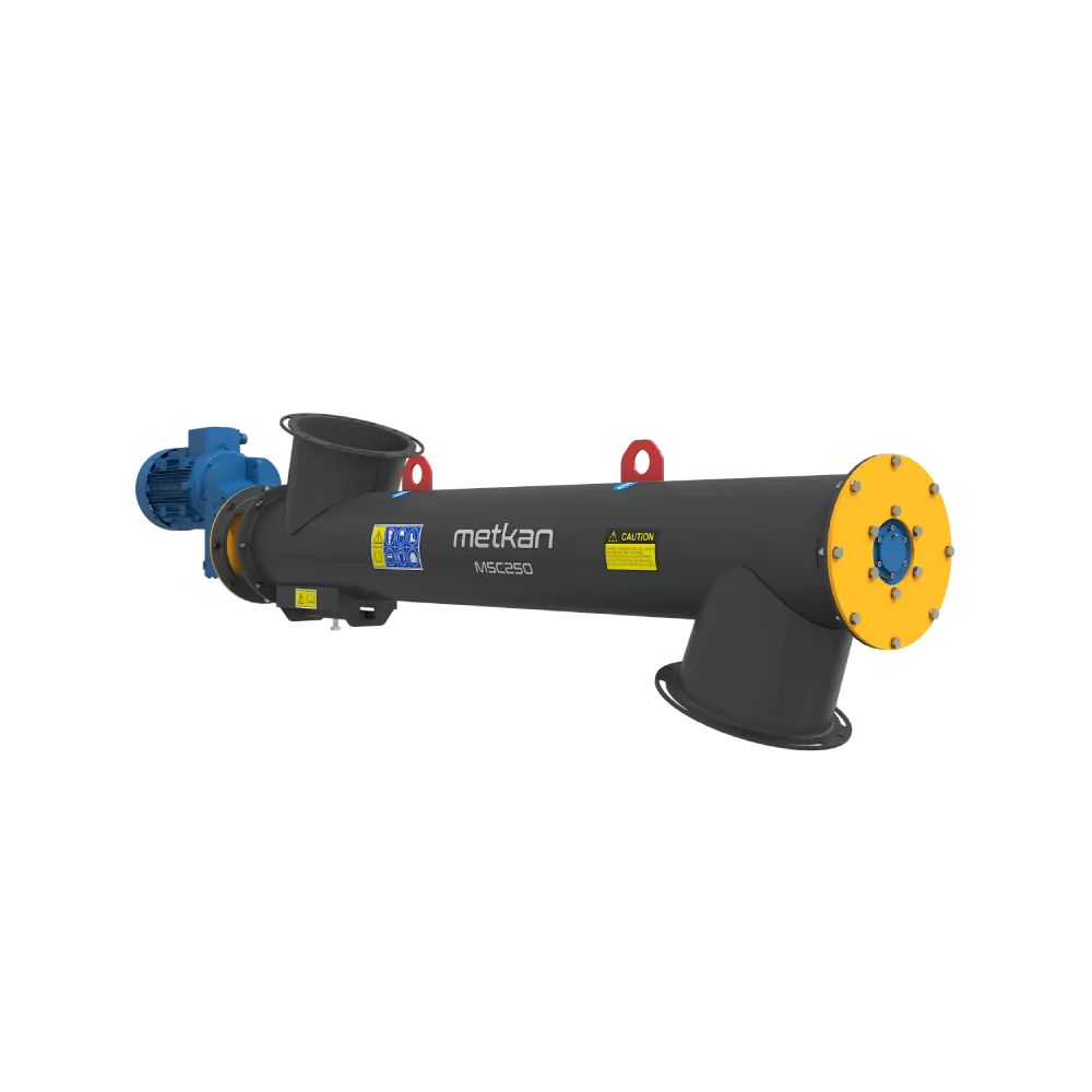
Calculated volume is unavailable when feed is irregular
The formula assumes a continuous, controlled supply at the inlet. Hopper bridging, aerated powder, surging discharge or an undersized inlet can leave the screw partly filled on some revolutions. Conversely, material backing up at the outlet turns the conveyor into a forced feeder and increases motor load. Distinguish a conveying screw from a dosing screw: the former transfers material, while the latter manages flow with a control system. Actual line capacity is limited by the lowest sustainable rate among the inlet, conveyor and discharge elements.
One factor cannot describe inclination and material behaviour
As inclination increases, material rollback on the flight and rotation inside the casing change, so usable capacity generally departs from the horizontal value. Particle friction, cohesion, moisture, aeration, temperature, abrasiveness and size distribution also affect fill and power demand. Worn flights, increased casing clearance or deposits can create leakage flow absent from the calculation. ISO 7119 covers drive-power calculation for regularly fed horizontal and moderately inclined conveyors; inclinations above 20°, vertical conveying, extracting, mixing and similar special duties are outside its scope. Do not directly scale the simple formula beyond those limits.
Field verification: make three steady measurements
Once production is stable, weigh the net mass conveyed over a known time and convert it to an hourly value with Qmeasured = mass / time. Make at least three measurements with the same product, speed and hopper level, recording spread as well as the average. Note rpm, motor current, inclination, hopper level, product moisture and visible fill during each run. If measured flow is below the theoretical result, first check regular inlet filling, then outlet build-up, reverse flow, flight-to-casing clearance and actual speed. Normal motor current alone does not prove that the target flow has been achieved.
Interpret the difference between theoretical and measured values
The Qmeasured / Qtheoretical ratio is not an acceptance criterion by itself, but it indicates the direction of the problem. If it is consistently low in every repeat, reassess the assumed fill, inclination effect or geometric leakage. If results are widely scattered, investigate unstable inlet flow, hopper level or material properties. If flow remains near target while motor current rises, inspect friction, bearings, alignment or material build-up. This separates a process limitation from a mechanical limitation before increasing screw diameter.
Which data is needed for a proposal and model selection?
For model selection, state both the target cubic metres per hour and tonnes per hour. Loose and compacted bulk density, particle-size distribution, moisture, temperature, flow behaviour and abrasiveness must be assessed together with conveyor length, inclination, inlet and outlet arrangement, duty time and cleaning needs. For a retrofit, also provide actual speed, motor current and a timed weighing result. These data reveal whether the right decision is to increase diameter, change feeding or speed, or adopt another conveying principle.
Sources and calculation note
The example only demonstrates the method and the effect of its variables. It cannot be used as a machine-capacity, motor-power or performance guarantee until the actual material, feed, inclination, casing and operating conditions are verified.
- Metkan MSC — Screw conveyor technical product page
- ISO 7119:1981 — Screw conveyors, design rules for drive power
- Owen & Cleary — Prediction of screw conveyor performance using DEM
- Owen & Cleary — DEM and laboratory comparison for screw conveyors
- VDI 2330 Part 2 — Horizontal and lightly inclined screw conveyors