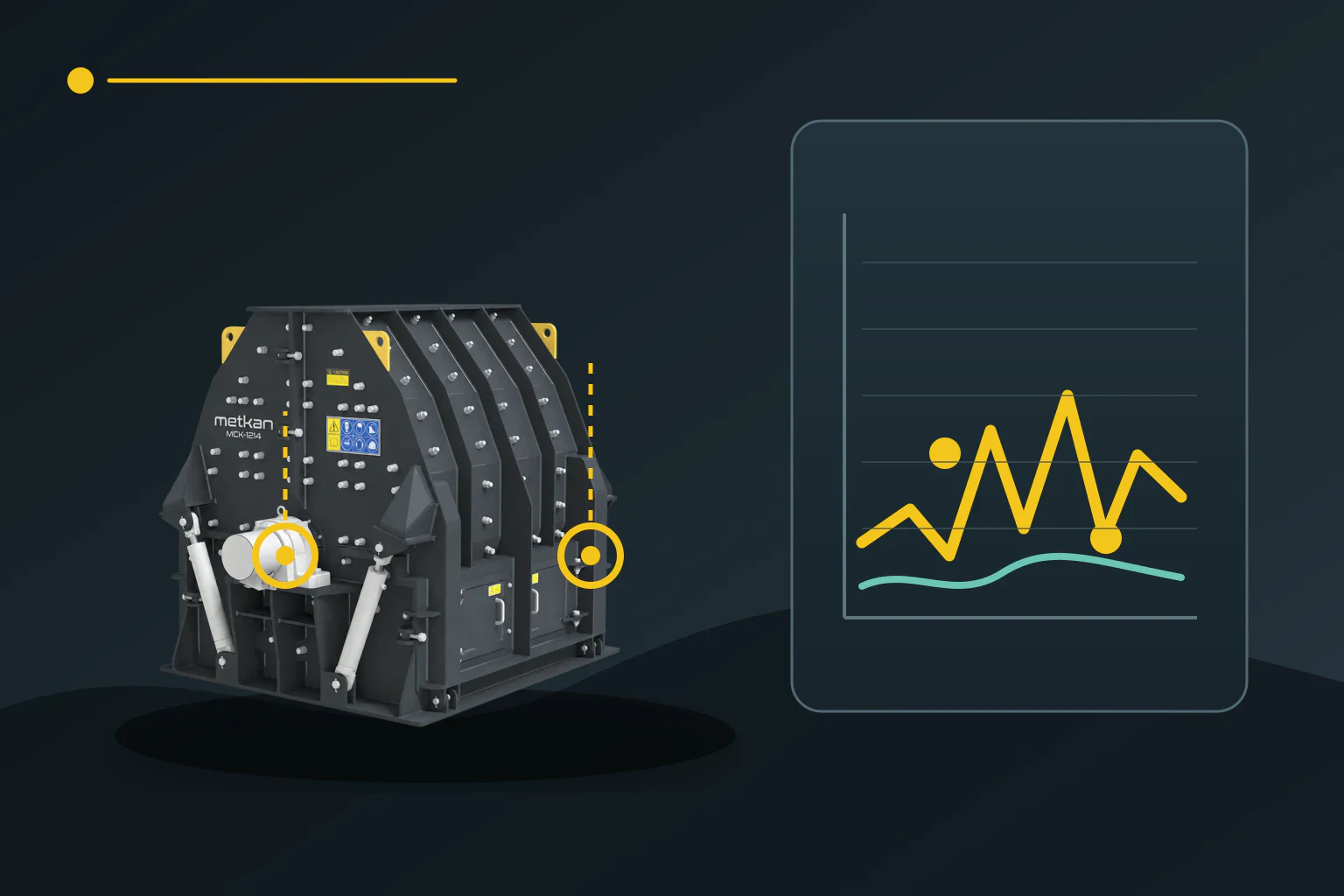
When a hammer crusher begins to vibrate unusually under normal feed, the first question is often whether the rotor has lost balance. The same symptom can also arise from a loose base, bearing damage, a belt or pulley problem, or feed accumulating on one side. A sound diagnosis comes from comparable data taken at the same speed and load, not from one isolated reading.
Make the measurements comparable
Start with a reference record from a condition the plant considers healthy. At both drive-end and non-drive-end bearing housings, record horizontal, vertical and axial directions together with motor speed, crusher speed, feed state and product type. A different sensor position or mounting method changes the trend. ISO 20816-1:2026 considers both vibration magnitude and change from a steady value, so readings from different days should not be compared directly unless the measurement point and operating condition are controlled.
Records taken at no load, steady load and, where feasible, during a controlled run-down help separate causes. If vibration rises only when material enters, investigate feed distribution, sticky moisture or build-up in the crushing chamber. Vibration that remains at no load and changes consistently with speed shifts attention to the rotor, pulley and fasteners. Guards stay in place during these comparisons; inspection follows the plant’s authorised maintenance and energy-isolation procedure.
Read frequency and mechanical evidence together
A dominant component at one times crusher running speed can be consistent with rotor imbalance, but it is not proof by itself. Looseness, misalignment or structural resonance can amplify the same region. Compare amplitude and phase between the two bearing points, direction-to-direction differences and behaviour as speed changes. The ISO 21940 series provides a framework for rotor balancing and error assessment; field correction must follow a method suitable for the rotor geometry and the manufacturer’s instructions.
Local bearing damage often creates repetitive high-frequency impulses hidden among crushing impacts. Overall vibration alone is therefore insufficient; inspect the time waveform, envelope information and repetition pattern referenced to speed. Research on a heavy-duty ore hammer crusher likewise shows why spectral methods may be needed to separate periodic bearing components from process impacts. Record lubrication condition, temperature and clearance observations alongside vibration data.
Match the symptom to likely causes
The table below is a decision sequence, not a definitive diagnosis from any single row. Reproduce the operating condition first, then check whether mechanical inspection and measurement support the same cause. If a missing or heavily worn hammer is found on one side while the running-speed component has risen, rotor mass distribution becomes a leading candidate. If only loose bolts are found, address the joint and foundation stiffness before considering a balance correction.
| Observation | Priority check | Verification |
|---|---|---|
| Dominant running-speed component with a consistent rise at both bearings | Hammer mass distribution, rotor and pulley | Amplitude and phase during no-load/speed change plus mechanical inspection |
| High in one direction with joint movement or knocking | Foundation, anchors, bearing feet and soft foot | Repeat the measurement after joint/contact correction |
| Repeated high-frequency impulses with a temperature change | Bearing, lubrication and bearing clearance | Envelope/time waveform, speed and physical inspection |
| Irregular rise only under feed | Feed distribution, sticking and chamber build-up | No-load/load records with the same product and process inspection |
Repeat the same test after correction
When hammers are replaced, preserve not only total weight but also opposing positions and the wear distribution around the rotor. Welding, grinding or trial weights on a rotor require an approved technical method. Balancing before checking pulley run-out, shaft connections and bearing fits can mask the real cause. Likewise, a new balance result may not remain valid while soft foot or a loose foundation is unresolved.
After intervention, repeat the test at the original sensor points with the same speed, product and feed condition. The objective is not merely to reduce one overall value; the spectrum, directional differences and relation between the two bearings should move toward the reference. If the result does not improve, revise the hypothesis and plan separate tests for feed distribution, resonance, bearings or the drive train. The maintenance decision then becomes a traceable cause-and-effect chain rather than the observation that vibration exists.
Technical sources
These sources support the measurement, trending and balancing approach. They do not provide an alarm threshold or field-performance claim for a specific Metkan machine.
- ISO 20816-1:2026 — Measurement and evaluation of machine vibration: general guidelines
- ISO 20816-3:2026 — In-situ vibration evaluation for industrial machines
- ISO 21940-14:2026 — Assessment of rotor balance errors
- Measurement — Local bearing-damage detection from vibration data in a heavy-duty ore crusher
- METAL 2020 — Effect of rotor balance on hammer-crusher operation